
Specifications
The purchaser may execute his judicious discretion in the choice of configuration and options.
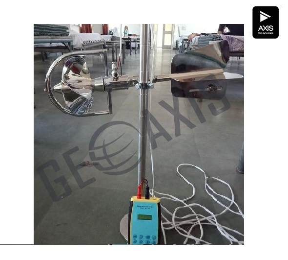
1. Current meter
current meter range 0.025 to 5 m/s (starting to maximum operational velocity)
propeller 2 to 4 blades
propeller diameter ≥0.1 to ≤0.2 m
propeller length about 0.1 m
- The current meter may be provided with one propeller or with a set of propellers that differ in their pitch and/or in their diameter.
- The propellers shall be made interchangeable.
- The propellers shall be made of cast material, e.g. bronze, polycarbonate or similar tough, high impact resistant and corrosion proof material.
- The response shall be instantly and consistent to all changes in velocity.
- The rate of change of the angular velocity of the propeller shall be synchronous with the rate of change of the flow velocity.
- Propellers of the same model shall be interchangeable without affecting calibration.
- The propellers shall be uniquely identifiable by engraved serial number.
| materials | all materials of the current meter and combinations thereof shall | |
| be corrosion proof | ||
| bearing | low friction, field replaceable without affecting the calibration | |
| rotation sensor | reed switch closure, one closure per revolution | |
| accuracy | for velocities up to 0.3 m/s | 1 % Full Scale |
| for velocities >0.3 m/s | 0.5 % Full Scale |
| From a cable | suspension cable with single integrated electrical wire for | |
| suspension cable | rotation sensor and bottom detector | |
| length | 30 m | |
| diameter | 2.5 to 3.5 mm | |
| electrical cable | from winch to counter, 7 m | |
| cable torque | torque free suspension cable |
The suspension cable should not exert any torque that may adversely affect the alignment of the flow sensor into the direction of flow. In particular in case a heavy suspension weight is used, there is a risk of cable induced torque.
suspension-rod for cable suspended measurements with light weight sinkers
The suspension rod shall have sufficient freedom of movement to allow it to accommodate to inclination of the suspension cable under high current velocities.
inclination range -45° (forward) to 10° (backward) from vertical.
tail fin length >0.6 m beyond the attach point of the suspension
The tail fin shall be capable of aligning the current meter in the direction of flow and keep it stable in that position throughout the full velocity range.
Integrated Bottom sensor is required
- Fish weight
model USGS Columbus or similar
material lead
| finish | smooth, painted surface |
| mass of fish weights | 25Kg- 2 no. and 50 kg-1 no Per set. |
| The fish weight may be integrated in the instrument or an addition below the instrument. | |
| bottom detector | the bottom detector shall be small and sturdy |
| bottom detection | bottom detection will be signalled by permanently closing a reed |
| switch. That switch will override the rotation sensor switch. The | |
| bottom detection signal will be sent on the same integrated wire | |
| as the rotation signals. | |
| suspension | bar, fitting current meter and cable terminal |
Accessories
- standard instrument tools
- spare bearings
- carrying case for current meter with counter
- carrying case for fish weight(s)
Consumables
- bearing oil